The DC motor has many advantages regarding starting and speed control. Therefore, it is a key component in the educational content in all specialties of mechanical engineering, such as vehicle engineering, mechatronics engineering, mechanical design, manufacture and automation. The control technology for the DC motor is very mature and many textbooks and other published literature have discussed its fundamentals, control methods and applications. There are some DC motor software simulation models that can be used directly to design and analyse DC motor applications. The models make excellent material for education. Computer simulation is a powerful tool for education about the characteristics of DC motors. Software packages that can be used for DC motor research and education include MATLAB . Direct current motors can be divided into separately excited DC motors, shunt-wound DC motors, series-wound DC motors and compound-wound DC motors. The separately excited DC motor is typical and always taught at universities. Described in this article is the simulation of a separately excited DC motor, including starting, speed control and braking, as well as an analysis of the results.
A MODEL OF THE SEPARATELY EXCITED DC MOTOR
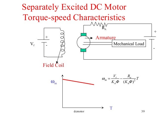
The equivalent circuit of the separately excited DC motor. Ia and If are the armature and field currents, Ra and La are the armature resistance and inductance, Rf and Lf are the field resistance and inductance, U and Uf are armature and field voltages, n and ω are the speed in r/min and rad/s, respectively, E is the back EMF (electromotive force) and Te is the electromagnetic torque.
SIMULATION OF STARTING THE MOTOR
At the beginning of starting the motor, the speedω = 0 and the back-EMF E = 0 . If the full voltage is applied to the armature terminals, the armature current Ia will be excessively heavy.The armature current is very heavy until the rotor runs up to full speed.
SIMULATION OF THE SPEED REGULATION
Three factors on the right side can be adjusted to control the speed, producing three basic speed regulation methods. A first involves adjustment of the applied terminal voltage, called armature voltage control. A second is field flux control. A third method involves the use of an external resistor connected in the armature circuit, called armature resistance control.
SIMULATION OF BRAKING
There are three braking methods: regenerative braking, plugging or reverse current braking, and dynamic braking or rheostatic braking. If the speed exceeds the no-load value, regenerative braking works. In rheostatic braking, an external resistance is connected in the armature in place of the DC supply. Plugging or reverse current braking is by reversing the power lines.

No comments:
Post a Comment