Saturday, 12 January 2019
Saturday, 20 January 2018
Pantograph (transport)
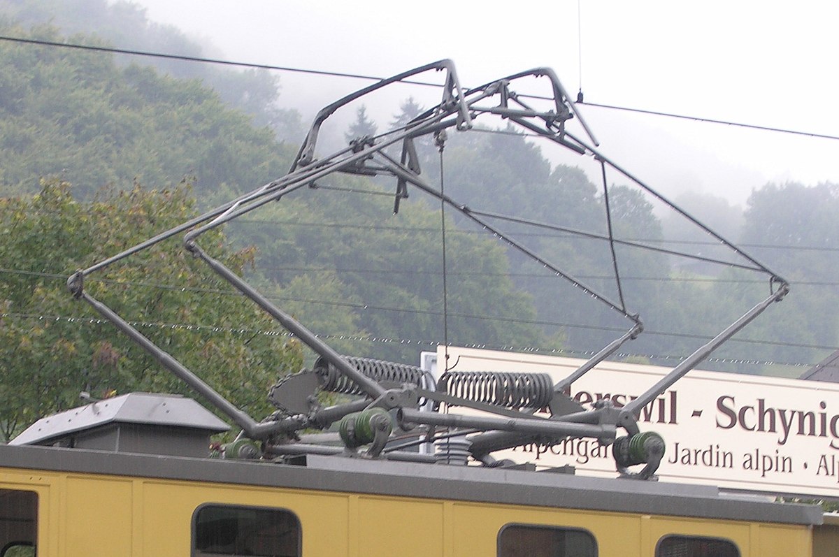
A pantograph (or "pan") is an apparatus mounted on the roof of an electric train, tram or electric bus[1] to collect power through contact with an overhead catenary wire. It is a common type of current collector. Typically, a single wire is used, with the return current running through the track. The term stems from the resemblance of some styles to the mechanical pantographs used for copying handwriting and drawings.

The pantograph, with a low-friction, replaceable contact strip to minimise lateral stress on the contact wire, was invented in 1879 by Walter Reichel, chief engineer at Siemens & Halske in Germany.[2][3] A flat slide-pantograph was invented in 1895 at the Baltimore and Ohio Railroad[4]
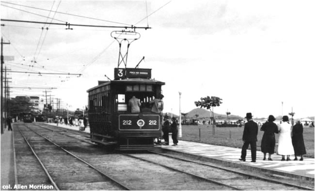
The familiar diamond-shaped roller pantograph was invented by John Q. Brown of the Key System shops for their commuter trains which ran between San Francisco and the East Bay section of the San Francisco Bay Area in California.[5][6] They appear in photographs of the first day of service, 26 October 1903.[7] For many decades thereafter, the same diamond shape was used by electric-rail systems around the world and remains in use by some today.
The pantograph was an improvement on the simple trolley pole, which prevailed up to that time, primarily because the pantograph allows an electric-rail vehicle to travel at much higher speeds without losing contact with the overhead lines.
Modern use
The most common type of pantograph today is the so-called half-pantograph (sometimes 'Z'-shaped), which evolved to provide a more compact and responsive single-arm design at high speeds as trains got faster. Louis Faiveley invented this type of pantograph in 1955.[8] The half-pantograph can be seen in use on everything from very fast trains (such as the TGV) to low-speed urban tram systems. The design operates with equal efficiency in either direction of motion, as demonstrated by the Swiss and Austrian railways whose newest high performance locomotives, the Re 460 and Taurus, operate with them set in the opposite direction. The geometry and shape of the pantographs are specified by the EN 50367/IEC 60486 - Railway applications - Current collection systems - Technical criteria for the interaction between pantograph and overhead line.[9]
Technical details

The electric transmission system for modern electric rail systems consists of an upper, weight-carrying wire (known as a catenary) from which is suspended a contact wire. The pantograph is spring-loaded and pushes a contact shoe up against the underside of the contact wire to draw the current needed to run the train. The steel rails of the tracks act as the electrical return. As the train moves, the contact shoe slides along the wire and can set up standing waves in the wires which break the contact and degrade current collection. This means that on some systems adjacent pantographs are not permitted.

Pantographs are the successor technology to trolley poles, which were widely used on early streetcar systems. Trolley poles are still used by trolleybuses, whose freedom of movement and need for a two-wire circuit makes pantographs impractical, and some streetcar networks, such as the Toronto streetcar system, which have frequent turns sharp enough to require additional freedom of movement in their current collection to ensure unbroken contact. However, many of these networks, including Toronto's, are undergoing upgrades to accommodate pantograph operation.
Pantographs with overhead wires are now the dominant form of current collection for modern electric trains because, although more fragile than a third-rail system, they allow the use of higher voltages.
Pantographs are typically operated by compressed air from the vehicle's braking system, either to raise the unit and hold it against the conductor or, when springs are used to effect the extension, to lower it. As a precaution against loss of pressure in the second case, the arm is held in the down position by a catch. For high-voltage systems, the same air supply is used to "blow out" the electric arc when roof-mounted circuit breakers are used.[10][11]
Single- and double-arm pantographs
.JPG)

Pantographs may have either a single or a double arm. Double-arm pantographs are usually heavier, requiring more power to raise and lower, but may also be more fault-tolerant.
On railways of the former USSR, the most widely used pantographs are those with a double arm ("made of two rhombs"), but since the late 1990s there have been some single-arm pantographs on Russian railways. Some streetcars use double-arm pantographs, among them the Russian KTM-5, KTM-8, LVS-86 and many other Russian-made trams, as well as some Euro-PCC trams in Belgium. American streetcars use either trolley poles or single-arm pantographs.
Metro systems and overhead lines

Most rapid transit systems are powered by a third rail, but some use pantographs, particularly ones that involve extensive above-ground running. Hybrid metro-tram or 'pre-metro' lines whose routes include tracks on city streets or in other publicly accessible areas, such as line 51 of the Amsterdam Metro, the MBTA Green Line, RTA Rapid Transit in Cleveland, and San Francisco's Muni Metro, naturally must use overhead wire, since a third rail would normally obstruct street traffic and present too great a risk of electrocution.
Among the various exceptions are several tram systems, such as the ones in Bordeaux, Angers, Reims and Dubai that use a proprietary underground system developed by Alstom, called APS, which only applies power to segments of track that are completely covered by the tram. This system was originally designed to be used in the historic centre of Bordeaux because an overhead wire system would cause a visual intrusion. Similar systems that avoid overhead lines have been developed by Bombardier, AnsaldoBreda, CAF, and others. These may consist of physical ground-level infrastructure, or use energy stored in battery packs to travel over short distances without overhead wiring.
Overhead pantographs are sometimes used as alternatives to third rails because third rails can ice over in certain winter weather conditions. The MBTA Blue Line uses pantograph power for the entire section of its route that runs on the surface, while switching to third rail power before entering the underground portion of its route. The entire metro systems of Madrid, Barcelona, Shanghai, Hong Kong, Seoul, Kobe, Fukuoka, Sendai, and Delhi use overhead wiring and pantographs (as well as certain lines of the metro systems in Beijing, Chongqing, Tokyo, Osaka, Nagoya, and Sapporo). Pantographs were also used on the Nord-Sud Company rapid transit lines in Paris until the other operating company of the time, Compagnie du chemin de fer métropolitain de Paris bought out the company and replaced all overhead wiring with the standard third rail system used on other lines.
Numerous railway lines use both third rail and overhead power collection along different portions of their routes, generally for historical purposes. They include the North London lineand West London lines of London Overground, four of the five lines in the Rotterdam Metro network, and the Chicago Transit Authority's Yellow Line. In this last case, the overhead portion was a remnant of the Chicago North Shore and Milwaukee Railroad's high-speed Skokie Valley Route,[12] and was the only line on the entire Chicago subway system to utilize pantograph collection for any length. As such, the line required railcars that featured pantographs as well as third rail shoes, and since the overhead was a very small portion of the system, only a few cars would be so equipped. The changeover occurred at the grade crossing at East Prairie, the former site of the Crawford-East Prairie station. Here, trains bound for Dempster-Skokie would raise their pantographs, while those bound for Howard would lower theirs, doing so at speed in both instances. In 2005, due to the cost and unique maintenance needs for what only represents a very small portion of the system, the overhead system was removed and replaced with the same third rail power as that used throughout the system, which allows all of Chicago's railcars to operate on the line, and the pantographs removed from the Skokie equipped cars.
Until 2010 the Oslo Metro line 1 changed from third rail to overhead line power at Frøen station. Due to the many level crossings, it was deemed difficult to install a third rail on the rest of the older line's single track.[13] After 2010 third rails are used in spite of level crossings. The third rails have gaps, but there are two contact shoes.
Inclined pantographs

On lines where open wagons are loaded from above the catenary wire may be offset to allow this; the pantographs are then mounted at an angle to the vertical.[14]
Weaknesses
Contact between a pantograph and an overhead catenary wire is usually assured through a block of graphite. This material conducts electricity while working as a lubricant. As graphite is brittle, pieces can break off during operation. Bad pantographs can seize the overhead wire and tear it down. So there is a two way influence where bad wires can damage the pantograph and bad pantographs can damage the wires. To prevent this, a pantograph monitoring station can be used. At sustained high speeds (above 300 kilometres per hour (190 mph)) friction can cause the contact strip to become red hot, which causes excessive arcing, and fail.[15]
In the UK, the pantographs (Brecknell Willis, Stone Faiveley etc.) of vehicles are raised by air pressure, and the graphite contact "carbons" create an air gallery in the pantograph head which release the air if a graphite strip is lost, activating the automatic drop device and lowering the pantograph to prevent damage. Newer electric traction units may use more sophisticated methods involving microprocessors which detect the disturbances caused by arcing at the point of contact if the graphite strips are damaged. There are not always two pantographs on an Electrical Multiple Unit but in cases where there are the other one can be used if one is damaged, an example of this situation would be a British Rail Class 387. The rearmost pantograph in relation to the direction of travel is often used as to avoid damaging both pantographs in case of entanglements: if the front pantograph was used, debris from an entanglement could cause damage to the rear pantograph, rendering both pantographs and the vehicle inoperable.
Bow collector
A bow collector is one of the three main devices used on tramcars to transfer electric current from the wires above to the tram below. While once very common in continental Europe, it was replaced by the pantograph or the trolley pole, itself often later replaced by the pantograph.
Origins
When the bow collector was first conceived by German inventor Ernst Werner von Siemens in the late 1880s, American inventor Frank J. Sprague of Virginia had just patented his trolley pole system of current collection from an overhead wire. To avoid contravening this patent, the Siemens company was forced to design its own, unique form of current collection, namely the bow collector. The bow collector was first used by the Siemens electric company in its early electric tramcars in either the late 1880s or early 1890s. The Hobart electric tramway system - the first of its kind in the Southern Hemisphere, opened in 1893 - used Siemens cars with very early bow collectors. Many other continental European and some British tramway systems, including Leeds and Glasgow, also used this method.
Construction

The bow collector is one of the simplest and most reliable methods of current collection used on tramways. The very earliest versions were simply very heavy-gauge wire or steel bars bent into a rectangular shape and mounted long-side-down on the tramcar roof. The height of the collector was such that its top edge would scrape along the wire above. The top section is made of a 1-inch broad (or thereabouts) steel rod, machined to have a bow-shaped cross section, hence the name. This bow shaped rod is referred to as the 'collector plate', and in later models may be up to several inches wide. Unlike many trolley poles, the bow collector does not normally have a revolving base (one exception was in Rome, where the entire assembly could be revolved), but is rather fixed centrally to the tramcar roof.
In the late 1900s the simple framing methods mentioned above were gradually replaced by more complex and sophisticated methods, but the general mode of operation remained the same. The changes of design are most noticeable on systems where both double- and single-deck cars were used on the same system. Single deck trams usually have tall and lightly constructed collectors with complicated frames to support the heavy cast-steel collector plate, while double deck cars usually have heavier collectors with less complicated frames.
To maintain good electrical contact, the bow collector must exert quite strong pressure on the wire above, and so complicated systems of springs or weights were put into use to ensure good electrical contact, and hence efficient operation was maintained.
The steel rails on the tracks act as the electrical return.
Operation
Properly the bow collector should be mounted in such a way so that the top edge of the collector plate would rise several inches above the wire when the collector frame is standing straight up. Thus the collector usually leans opposite to the direction of travel; when the time comes to travel in the opposite direction, the collector must be swung over. To allow this to happen, the overhead wire must be raised by several inches at places where the bows are swung over, such as terminals and turn-outs. This operation is usually achieved by ropes and pulleys. The collector is folded down to a horizontal position when the car is not in use.
Some early cars had no means to swing the bows over. It was thought that this would happen automatically when the tramcar started travelling the other way, but collectors such as these were a failure.
Most Soviet trams (of which some are still in use in ex-USSR) had no means to swing the bows over. These trams were not designed to travel two ways. Another example is KTV-55-2 tramcar which had two bow collectors for the two directions of travelling.
Advantages and modern usage
The bow collector has fewer moving parts than the trolley pole, but is heavier and sometimes more complicated to construct. The construction of overhead wires for bow collectors is simpler than trolley pole wiring. As bow collectors do not have revolving mountings, the collector cannot jump off the wire or follow the wrong one at intersections, as trolley poles sometimes do. Thus overhead 'frogs' and guides for trolley poles are not necessary with bow collectors. Bow collectors are, however, much noisier than trolley poles.
The overhead wires for bow collectors are stretched tighter than for trolley poles, and straight sections are 'staggered', that is, the wire does not run completely straight down the centreline of the track, but rather zig-zags slightly across a small distance. This distributes wear across the bow collector's collector plate, and extends the collector's life.
In addition to some vintage tramways, bow collectors are still used in some tram systems in the former Soviet Union, e. g., in Kazan, Minsk, and Dzerzhinsk.
Rigid collectors

On the Isle of Man, the Snaefell Mountain Railway's implementation is unusual in that the overhead wire is slack and free to hang in a catenary. Hopkinson bow collectors are used, to avoid problems with trolley poles in high winds on the mountainous route[1] – the Snaefell line also uses a Fell rail for braking. Each car has two rigidly vertical bow collectors, with a slack wire above them making contact under its own weight. The collectors are not quite tall enough to make contact with the wire at its suspension points. They are far enough apart, relative to the pole spacing, so that while one is out of contact with the wire the other is mid span and making good contact. The collectors can only be lowered by unbolting them at roof level, whilst the power is off. This inability to isolate them easily hampered fire fighting when car 5 caught fire in 1970.[citation needed]
Similar collectors were also used at first on the nearby and slightly earlier Manx Electric Railway. They gave trouble initially with poor contact and so the slack wire system was developed. A tensioned wire usually gave a good contact but broke contact when the collector passed the pole. Slackening the wire and deliberately lifting it up clear of the collector at the poles allowed its weight to give a reliable contact over the other collector, spaced to be at the midpoint between poles. A revised collector was in use within the first few years, by 1900. A small hinged bow frame was placed on top of the fixed uprights, giving a sprung contact.[2] Bow collectors did not last though and were replaced with trolley poles.
Regenerative brake

Regenerative braking is an energy recovery mechanism which slows a vehicle or object by converting its kinetic energy into a form which can be either used immediately or stored until needed. This contrasts with conventional braking systems, where the excess kinetic energy is converted to unwanted and wasted heat by friction in the brakes, or with dynamic brakes, where energy is recovered by using electric motors as generators but is immediately dissipated as heat in resistors. In addition to improving the overall efficiency of the vehicle, regeneration can greatly extend the life of the braking system as its parts do not wear as quickly.
General
The most common form of regenerative brake involves an electric motor as an electric generator. In electric railways the electricity generated is fed back into the supply system. In battery electric and hybrid electric vehicles, the energy is stored chemically in a battery, electrically in a bank of capacitors, or mechanically in a rotating flywheel. Hydraulic hybridvehicles use hydraulic motors to store energy in the form of compressed air. In a fuel cell powered vehicle, the electric energy generated by the motor is used to break waste water down into oxygen, and hydrogen which goes back into the fuel cell for later reuse.
Practical regenerative braking
Regenerative braking is not by itself sufficient as the sole means of safely bringing a vehicle to a standstill, or slowing it as required, so it must be used in conjunction with another braking system such as friction-based braking.
- The regenerative braking effect drops off at lower speeds, and cannot bring a vehicle to a complete halt reasonably quickly with current technology.
- Current regenerative brakes do not immobilize a stationary vehicle; physical locking is required, for example to prevent vehicles from rolling down hills.
- Many road vehicles with regenerative braking do not have drive motors on all wheels (as in a two-wheel drive car); regenerative braking is normally only applicable to wheels with motors. For safety, the ability to brake all wheels is required.
- The regenerative braking effect available is limited, and mechanical braking is still necessary for substantial speed reductions, to bring a vehicle to a stop, or to hold a vehicle at a standstill.
Regenerative and friction braking must both be used, creating the need to control them to produce the required total braking. The GM EV-1 was the first commercial car to do this. In 1997 and 1998 engineers Abraham Farag and Loren Majersik were issued two patents for this brake-by-wire technology.[2][3]
Early applications commonly suffered from a serious safety hazard: in many early electric vehicles with regenerative braking, the same controller positions were used to apply power and to apply the regenerative brake, with the functions being swapped by a separate manual switch. This led to a number of serious accidents when drivers accidentally accelerated when intending to brake, such as the runaway train accident in Wädenswil, Switzerland in 1948, which killed twenty-one people.
Conversion to electric energy: the motor as a generator
.jpg)
Electric motors, when used in reverse function as generators, convert mechanical energy into electrical energy. Vehicles propelled by electric motors use them as generators when using regenerative braking, braking by transferring mechanical energy from the wheels to an electrical load.
Early examples of this system were the front-wheel drive conversions of horse-drawn cabs by Louis Antoine Krieger in Paris in the 1890s. The Krieger electric landaulet had a drive motor in each front wheel with a second set of parallel windings (bifilar coil) for regenerative braking.[4] In England, "automatic regenerative control" was introduced to tramway operators by John S. Raworth’s Traction Patents 1903–1908, offering them economic and operational benefits[5] [6] [7] as explained in some detail by his son Alfred Raworth. These included tramway systems at Devonport (1903), Rawtenstall, Birmingham, Crystal Palace-Croydon (1906), and many others. Slowing the speed of the cars or keeping it in control on descending gradients, the motors worked as generators and braked the vehicles. The tram cars also had wheel brakes and track slipper brakes which could stop the tram should the electric braking systems fail. In several cases the tram car motors were shunt wound instead of series wound, and the systems on the Crystal Palace line utilized series-parallel controllers.[clarification needed][8] Following a serious accident at Rawtenstall, an embargo was placed on this form of traction in 1911; the regenerative braking system was reintroduced twenty years later.[7] Regenerative braking has been in extensive use on railways for many decades. The Baku-Tbilisi-Batumi railway (Transcaucasus Railway or Georgian railway) started utilizing regenerative braking in the early 1930s. This was especially effective on the steep and dangerous Surami Pass.[9] In Scandinavia the Kiruna to Narvik electrified railway carries iron ore on the steeply-graded route from the mines in Kiruna, in the north of Sweden, down to the port of Narvik in Norway to this day. The rail cars are full of thousands of tons of iron ore on the way down to Narvik, and these trains generate large amounts of electricity by regenerative braking, with a maximum recuperative braking force of 750 kN. From Riksgränsen on the national border to the Port of Narvik, the trains[10] use only a fifth of the power they regenerate.[not in citation given] The regenerated energy is sufficient to power the empty trains back up to the national border.[11][not in citation given] Any excess energy from the railway is pumped into the power grid to supply homes and businesses in the region, and the railway is a net generator of electricity.[citation needed]
Electric cars used regenerative braking since the earliest experiments, but this was often a complex affair where the driver had to flip switches between various operational modes in order to use it. The Baker Electric Runabout and the Owen Magnetic were early examples, which used many switches and modes controlled by an expensive "black box" or "drum switch" as part of their electrical system.[12][13] These, like the Krieger design, could only practically be used on downhill portions of a trip, and had to be manually engaged.
Improvements in electronics allowed this process to be fully automated, starting with 1967's AMC Amitron experimental electric car. Designed by Gulton Industries[14] the motor controller automatically began battery charging when the brake pedal was applied. Many modern hybrid and electric vehicles use this technique to extend the range of the battery pack, especially those using an AC drive train (most earlier designs used DC power).
Electric railway vehicle operation
In 1886 the Sprague Electric Railway & Motor Company, founded by Frank J. Sprague, introduced two important inventions: a constant-speed, non-sparking motor with fixed brushes, and regenerative braking.
During braking, the traction motor connections are altered to turn them into electrical generators. The motor fields are connected across the main traction generator (MG) and the motor armatures are connected across the load. The MG now excites the motor fields. The rolling locomotive or multiple unit wheels turn the motor armatures, and the motors act as generators, either sending the generated current through onboard resistors (dynamic braking) or back into the supply (regenerative braking). Compared to electro-pneumatic friction brakes, braking with the traction motors can be regulated faster improving the performance of wheel slide protection.
For a given direction of travel, current flow through the motor armatures during braking will be opposite to that during motoring. Therefore, the motor exerts torque in a direction that is opposite from the rolling direction.
Braking effort is proportional to the product of the magnetic strength of the field windings, multiplied by that of the armature windings.
Savings of 17%, and less wear on friction braking components, are claimed for Virgin Trains Pendolinos.[15] The Delhi Metro reduced the amount of carbon dioxide (CO
2) released into the atmosphere by around 90,000 tons by regenerating 112,500 megawatt hours of electricity through the use of regenerative braking systems between 2004 and 2007. It was expected that the Delhi Metro would reduce its emissions by over 100,000 tons of CO
2 per year once its phase II was complete, through the use of regenerative braking.[16]
Electricity generated by regenerative braking may be fed back into the traction power supply; either offset against other electrical demand on the network at that instant, used for head end power loads, or stored in lineside storage systems for later use.[17]
A form of what can be described as regenerative braking is used on some parts of the London Underground, achieved by having small slopes leading up and down from stations. The train is slowed by the climb, and then leaves down a slope, so kinetic energy is converted to gravitational potential energy in the station.[18] This is normally found on the deep tunnel sections of the network and not generally above ground or on the cut and cover sections of the Metropolitan and District Lines.
Comparison of dynamic and regenerative brakes

What are described as dynamic brakes ("rheostatic brakes" in the UK) on electric traction systems, unlike regenerative brakes, dissipate electric energy as heat rather than using it, by passing the current through large banks of variable resistors. Vehicles that use dynamic brakes include forklift trucks, diesel-electric locomotives, and trams. This heat can be used to warm the vehicle interior, or dissipated externally by large radiator-like cowls to house the resistor banks.
General Electric's experimental 1936 steam turbine locos featured true regeneration. These two locomotives ran the steam water over the resistor packs, as opposed to air cooling used in most dynamic brakes. This energy displaced the oil normally burned to keep the water hot, and thereby recovered energy that could be used to accelerate again.[19]
The main disadvantage of regenerative brakes when compared with dynamic brakes is the need to closely match the generated current with the supply characteristics and increased maintenance cost of the lines. With DC supplies, this requires that the voltage be closely controlled. The AC power supply and frequency converter pioneer Miro Zorič and his first AC power electronics have also enabled this to be possible with AC supplies. The supply frequency must also be matched (this mainly applies to locomotives where an AC supply is rectified for DC motors).
In areas where there is a constant need for power unrelated to moving the vehicle, such as electric train heat or air conditioning, this load requirement can be utilized as a sink for the recovered energy via modern AC traction systems. This method has become popular with North American passenger railroads where head end power loads are typically in the area of 500 kW year round. Using HEP loads in this way has prompted recent electric locomotive designs such as the ALP-46 and ACS-64to eliminate the use of dynamic brake resistor grids and also eliminates any need for any external power infrastructure to accommodate power recovery allowing self-powered vehicles to employ regenerative braking as well.
A small number of steep grade railways have used 3-phase power supplies and induction motors. This results in a near constant speed for all trains, as the motors rotate with the supply frequency both when driving and braking.
Conversion to mechanical energy
Kinetic energy recovery systems
Kinetic energy recovery systems (KERS) were used for the motor sport Formula One's 2009 season, and are under development for road vehicles. KERS was abandoned for the 2010 Formula One season, but re-introduced for the 2011 season. By 2013, all teams were using KERS with Marussia starting use for the 2013 season.[20] One of the main reasons that not all cars used KERS immediately is because it raises the car's center of gravity, and reduces the amount of ballast that is available to balance the car so that it is more predictable when turning.[21] FIA rules also limit the exploitation of the system. The concept of transferring the vehicle’s kinetic energy using flywheel energy storage was postulated by physicist Richard Feynman in the 1950s[22] and is exemplified in such systems as the Zytek, Flybrid,[23] Torotrak[24][25] and Xtrac used in F1. Differential based systems also exist such as the Cambridge Passenger/Commercial Vehicle Kinetic Energy Recovery System (CPC-KERS).[26]
Xtrac and Flybrid are both licensees of Torotrak's technologies, which employ a small and sophisticated ancillary gearbox incorporating a continuously variable transmission (CVT). The CPC-KERS is similar as it also forms part of the driveline assembly. However, the whole mechanism including the flywheel sits entirely in the vehicle’s hub (looking like a drum brake). In the CPC-KERS, a differential replaces the CVT and transfers torque between the flywheel, drive wheel and road wheel.
Use in motor sport
History

The first of these systems to be revealed was the Flybrid. This system weighs 24 kg and has an energy capacity of 400 kJ after allowing for internal losses. A maximum power boost of 60 kW (81.6 PS, 80.4 HP) for 6.67 seconds is available. The 240 mm diameter flywheel weighs 5.0 kg and revolves at up to 64,500 rpm. Maximum torque is 18 Nm (13.3 ftlbs). The system occupies a volume of 13 litres.[citation needed]
Two minor incidents have been reported during testing of KERS systems in 2008. The first occurred when the Red Bull Racing team tested their KERS battery for the first time in July: it malfunctioned and caused a fire scare that led to the team's factory being evacuated.[27] The second was less than a week later when a BMW Sauber mechanic was given an electric shock when he touched Christian Klien's KERS-equipped car during a test at the Jerez circuit.[28]
FIA

Formula One have stated that they support responsible solutions to the world's environmental challenges,[29] and the FIA allowed the use of 81 hp (60 kW; 82 PS) KERS in the regulations for the 2009 Formula One season.[30] Teams began testing systems in 2008: energy can either be stored as mechanical energy (as in a flywheel) or as electrical energy (as in a battery or supercapacitor).[31]
With the introduction of KERS in the 2009 season, four teams used it at some point in the season: Ferrari, Renault, BMW, and McLaren. During the season, Renault and BMW stopped using the system. Vodafone McLaren Mercedes became the first team to win a F1 GP using a KERS equipped car when Lewis Hamilton won the Hungarian Grand Prix on 26 July 2009. Their second KERS equipped car finished fifth. At the following race, Lewis Hamilton became the first driver to take pole position with a KERS car, his teammate, Heikki Kovalainen qualifying second. This was also the first instance of an all KERS front row. On 30 August 2009, Kimi Räikkönen won the Belgian Grand Prix with his KERS equipped Ferrari. It was the first time that KERS contributed directly to a race victory, with second placed Giancarlo Fisichella claiming "Actually, I was quicker than Kimi. He only took me because of KERS at the beginning".[32]
Although KERS was still legal in F1 in the 2010 season, all the teams had agreed not to use it.[33] New rules for the 2011 F1 season which raised the minimum weight limit of the car and driver by 20 kg to 640 kg,[34] along with the FOTA teams agreeing to the use of KERS devices once more, meant that KERS returned for the 2011 season.[35] This is still optional as it was in the 2009 season; in the 2011 season 3 teams elected not to use it.[20] For the 2012 season, only Marussia and HRT raced without KERS, and by 2013, with the withdrawal of HRT, all 11 teams on the grid were running KERS.
For the 2014 season, the power output of the MGU-K (The replacement of the KERS and part of the ERS system that also includes a turbocharger waste heat recovery system) increased from 60 kW to 120 kW and it is allowed to recover 2 mega-joules per lap. This was to balance the sport's move from 2.4 litre V8 engines to 1.6 litre V6 engines.[36] The fail-safe settings of the brake-by-wire system that now supplements KERS came under examination as a contributing factor in the crash of Jules Bianchi at the 2014 Japanese Grand Prix.
Autopart makers
Bosch Motorsport Service is developing a KERS for use in motor racing. These electricity storage systems for hybrid and engine functions include a lithium-ion battery with scalable capacity or a flywheel, a four to eight kilogram electric motor (with a maximum power level of 60 kW or 80 hp), as well as the KERS controller for power and battery management. Bosch also offers a range of electric hybrid systems for commercial and light-duty applications.[37]
Carmakers
Automakers including Honda have been testing KERS systems.[38] At the 2008 1,000 km of Silverstone, Peugeot Sport unveiled the Peugeot 908 HY, a hybrid electric variant of the diesel 908, with KERS. Peugeot planned to campaign the car in the 2009 Le Mans Series season, although it was not capable of scoring championship points.[39] Peugeot plans also a compressed air regenerative braking powertrain called Hybrid Air.[40][41]
Vodafone McLaren Mercedes began testing of their KERS in September 2008 at the Jerez test track in preparation for the 2009 F1 season, although at that time it was not yet known if they would be operating an electrical or mechanical system.[42] In November 2008 it was announced that Freescale Semiconductor would collaborate with McLaren Electronic Systems to further develop its KERS for McLaren's Formula One car from 2010 onwards. Both parties believed this collaboration would improve McLaren's KERS system and help the system filter down to road car technology.[43]
Toyota has used a supercapacitor for regeneration on Supra HV-R hybrid race car that won the 24 Hours of Tokachi race in July 2007.[44]
BMW has used regenerative braking on their E90 3 Series as well as in current models like F25 5 Series under the EfficientDynamics moniker.[45] Volkswagen have regenerative braking technologies under the BlueMotion brand in such models as the MK7 Golf and MK7 Golf Estate / Wagon models, other VW group brands like SEAT, Skoda and Audi.[46]
Motorcycles
KTM racing boss Harald Bartol has revealed that the factory raced with a secret kinetic energy recovery system (KERS) fitted to Tommy Koyama's motorcycle during the 2008 season-ending 125cc Valencian Grand Prix. This was against the rules, so they were banned from doing it afterwards.[47]
Bicycles
Regenerative braking is also possible on a non-electric bicycle. The EPA, working with students from the University of Michigan, developed the hydraulic Regenerative Brake Launch Assist (RBLA).[48] It is naturally available on electric bicycles with direct-drive hub motors.
Races
Automobile Club de l'Ouest, the organizer behind the annual 24 Hours of Le Mans event and the Le Mans Series is currently "studying specific rules for LMP1 that will be equipped with a kinetic energy recovery system."[49] Peugeot was the first manufacturer to unveil a fully functioning LMP1 car in the form of the 908 HY at the 2008 Autosport 1000 km race at Silverstone.[50]
Thermodynamics
KERS Flywheel
The energy of a flywheel can be described by this general energy equation, assuming the flywheel is the system:

Where:
- is the energy into the flywheel.
- is the energy out of the flywheel.
- is the change in energy of the flywheel.


An assumption is made that during braking there is no change in the potential energy, enthalpy of the flywheel, pressure or volume of the flywheel, so only kinetic energy will be considered. As the car is braking, no energy is dispersed by the flywheel, and the only energy into the flywheel is the initial kinetic energy of the car. The equation can be simplified to:

Where:
- is the mass of the car.
- is the initial velocity of the car just before braking.


The flywheel collects a percentage of the initial kinetic energy of the car, and this percentage can be represented by . The flywheel stores the energy as rotational kinetic energy. Because the energy is kept as kinetic energy and not transformed into another type of energy this process is efficient. The flywheel can only store so much energy, however, and this is limited by its maximum amount of rotational kinetic energy. This is determined based upon the inertia of the flywheel and its angular velocity. As the car sits idle, little rotational kinetic energy is lost over time so the initial amount of energy in the flywheel can be assumed to equal the final amount of energy distributed by the flywheel. The amount of kinetic energy distributed by the flywheel is therefore:


Regenerative braking has a similar energy equation to the equation for the mechanical flywheel. Regenerative braking is a two-step process involving the motor/generator and the battery. The initial kinetic energy is transformed into electrical energy by the generator and is then converted into chemical energy by the battery. This process is less efficient than the flywheel. The efficiency of the generator can be represented by:

Where:
- is the work into the generator.
- is the work produced by the generator.


The only work into the generator is the initial kinetic energy of the car and the only work produced by the generator is the electrical energy. Rearranging this equation to solve for the power produced by the generator gives this equation:

Where:
- is the amount of time the car brakes.
- is the mass of the car.
- is the initial velocity of the car just before braking.

The efficiency of the battery can be described as:

Where:


The work out of the battery represents the amount of energy produced by the regenerative brakes. This can be represented by:

Cars

In the case of internal combustion engines, the sketch of the DoE shows that average car efficiency amounts to less than 20%. We can see for ourselves that braking in proportion to the useful mechanic energy amounts to 6/13 i.e. 46% in towns, and 5/20 i.e. 25% on motorways.
As regards electric cars, the DoE explains that the efficiency between the electric motor and the wheels amounts to 60% [51] (however for the overall conversion see Embodied energy#Embodied energy in the energy field).
Let us consider the electric motor efficiency [Note 1] and the braking proportion in towns and on motorways .


Let us introduce which is the recuperated proportion of braking energy. Theoretically, it can reach up to 80%.[Note 2] Thus in the best case.


Under these circumstances, being the energy flux arriving at the electric engine, the energy flux lost while braking and the recuperated energy flux, an equilibrium is reached according to the equations


and


thus

It is as though the old energy flux was replaced by a new one

The expected gain amounts to

The higher the recuparation efficiency, the higher the recuperation.
The higher the efficiency between the electric motor and the wheels, the higher the recuperation.
The higher the braking proportion, the higher the recuperation.
Subscribe to:
Comments (Atom)